LED control using Arduino
In this tutorial, I’ll show you how to use an Arduino to control LEDs like turn on and off an LED connected to one of the Arduino’s digital pins. I’ll explain how to change the LEDs flashing rate, and how to change the pin that powers the LED.
Electrical signals
The Arduino communicates with modules and sensors by switching on and off electrical current. It’s very similar to the one’s and zero’s in binary code. When current is switched on, it’s known as a “HIGH signal”. That’s comparable to the “one” in binary code. When the current is switched off, that’s a “LOW signal”, which is similar to the zero in binary code. The length of time the current stays on or off can be changed from a microsecond up to many minutes.
Components :
- 1 x 220-ohm resistors
- A breadboard
- Connecting wires
- LED light
Almost any Arduino will work for this project, providing it has enough pins.
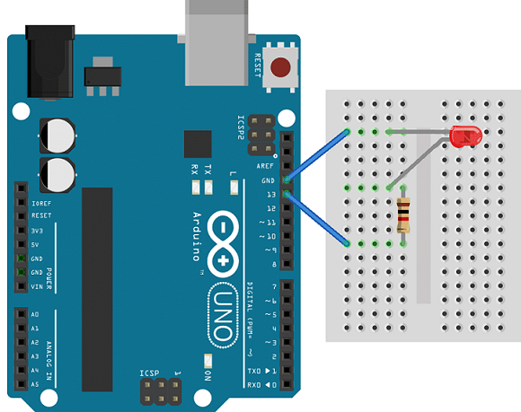
Connections:
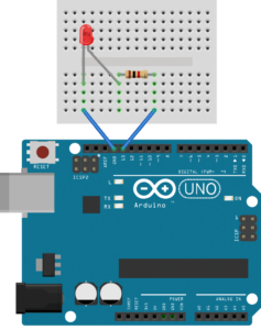
The Arduino has an on-board surface mount LED that’s hard wired to digital pin 13. You can connect any digital pin(8-13). Connect the anode (long leg) of LED to digital pins 13 (via a 220-ohm resistor). Connect the cathodes (short leg) to the Arduino’s ground.
To turn on an LED, the Arduino needs to send a HIGH signal to one of it’s pins. To turn off the LED, it needs to send a LOW signal to the pin.
Example Code
The code makes the digital pin 13 OUTPUT and Toggles it HIGH and LOW
void setup() {
  pinMode(13, OUTPUT);    // sets the digital pin 13 as output
}

void loop() {
  digitalWrite(13, HIGH); // sets the digital pin 13 on
  delay(1000);            // waits for a second
  digitalWrite(13, LOW);  // sets the digital pin 13 off
  delay(1000);            // waits for a second
}
You can also write this code as below,
int led_pin = 13;
void setup() {
  pinMode(led_pin, OUTPUT);    // sets the digital pin 13 as output
}

void loop() {
  digitalWrite(led_pin, HIGH); // sets the digital pin 13 on
  delay(1000);            // waits for a second
  digitalWrite(led_pin, LOW);  // sets the digital pin 13 off
  delay(1000);            // waits for a second
}
Upload any one code into your arduino.
The LED should now be blinking on and off at a rate of 1000 milliseconds (1000 milliseconds = 1 second).
pinMode(13, OUTPUT);
Configures the specified pin to behave either as an input or an output.
Syntax
pinMode(pin, mode)
Parameters
pin: The Arduino pin number to set the mode of.
mode: INPUT, OUTPUT, or INPUT_PULLUP. See the Digital Pins page for a more complete description of the functionality.
digitalWrite(13, HIGH);
Write a HIGH or a LOW value to a digital pin 13. If the pin has been configured as an OUTPUT with pinMode(), its voltage will be set to the corresponding value: 5V (or 3.3V on 3.3V boards) for HIGH, 0V (ground) for LOW.
If the pin is configured as an INPUT, digitalWrite() will enable (HIGH) or disable (LOW) the internal pullup on the input pin. It is recommended to set the pinMode() to INPUT_PULLUP to enable the internal pull-up resistor. See the Digital Pins tutorial for more information.
If you do not set the pinMode() to OUTPUT, and connect an LED to a pin, when calling digitalWrite(HIGH), the LED may appear dim. Without explicitly setting pinMode(), digitalWrite() will have enabled the internal pull-up resistor, which acts like a large current-limiting resistor.
Syntax
digitalWrite(pin, value)
Parameters
pin: the Arduino pin number.
value: HIGH or LOW.
Leave a Comment
(0 Comments)